Mfr Part # 4128
JUMPER WIRE M TO F 7.874" 10PCS
Kitronik Ltd.
License: See Original Project micro:bit
Courtesy of Kitronik Maker
Guide by Kitronik Maker
This Pedestrian Crossing project was submitted to us by Thomas Stratford. Thomas started this project to try out the pre-written code that came with the IET Pedestrian Crossing resource. The aim is to use the BBC micro:bit to develop a prototype for a pedestrian crossing for a local secondary school.
Thomas Stratford is an ICT Technician for the Misbourne School. When he isn’t fixing IT problems, he spends his time making, tinkering and building Electronics projects. He is currently learning about the recently released BBC micro:bit.
In order to create this project in the same way as the example below, you will need to source the following components: Parts List:
1 x Kitronik Prototyping System.
2 x Red LEDs.
Two Green LEDs.
An Orange LED.
1 x Piezo Sounder.
A x NPN Transistor.
1 x 2.2kΩ Resistor.
5 x Resistors suitable for your LED’s (I used 220Ω resistors).
Note: With the exception of the 5 x 220Ω resistors, all of the parts used in this Project can be found in the Kitronik Inventors Kit. If you have the Inventors Kit, you can substitute the 220Ω resistors for the 47Ω resistors that come with the Kit.
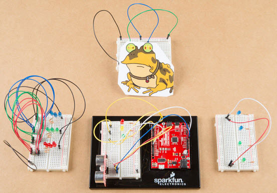
First, I connected three LED’s to P0, P1 & P2 via series resistors as show in the picture below. Stage 1 Suggested Breadboard Layout:
This worked well so I thought I would try adding two more LEDs via series resistors to ports (P8 & P12). I modified the pre-written program so that the two additional LEDs would also be controlled.
Stage 2 Suggested Breadboard Layout:
Stage 2 Completed Example:
The final part of this project was to add a piezo sounder to simulate the crossing beeper. I connected a piezo sounder to port (P16) via a driver transistor. I modified the code once more to add this functionality.
Stage 3 Suggested Breadboard Layout:
Stage 3 Completed Example:
Note: The Breadboard layout shows a buzzer with leads, but the completed example shows a buzzer that fits directly to the breadboard, therefore the wire link or jumper wire is connected differently. It would be better to follow the breadboard image layout as this is easier to follow. Code: The original code was written in Microsoft Touch Develop. This editor has since been taken out of commission and the code has been recreated in the Microsoft MakeCode editor, see below.
Microsoft MakeCode | Terms of Use | Privacy | Download
We would like to thank Thomas for sharing his excellent project with us. For up to the minute accounts of Thomas’ projects, follow him on Twitter: @MrTomsWorld.