Mfr Part # 1138
ADDRESS LED STRIP SERIAL RGB 4M
Adafruit Industries LLC
License: See Original Project Amplifiers Laser Cutters LED Strips Microcontrollers Wifi Wireless ESP32
Courtesy of Adafruit
Guide by Erin St Blaine
Overview
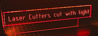
Layered laser-cut designs offer a unique opportunity to combine natural wood textures with the luminous glow of edge-lit acrylic. These downloadable designs are easy to find on the internet. Etsy.com has a huge selection of multi-layered files available, which you can download for $3-$5. Import the files into your laser cutter software and you can quickly create beautiful, layered art pieces that invoke nature and the spirit with intricate mandalas, animals, or sacred geometry.
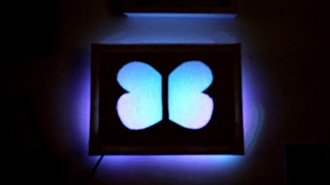
Naturally, adding lights makes all crafting projects better. The Tree of Life design I used has six layers, each with slight variations in shape that create a lovely depth to the finished artwork. I cut four of the layers from 1/8" plywood using the laser cutter at my local makerspace and then made the remaining two layers from 1/8" acrylic, which I laser-etched with the design instead of cutting, giving me the opportunity for two different glowing edge-lit areas within the design.
Add some NeoPixels LED lights and an Adafruit Sparkle Motion board and the result is absolutely stunning: I can create glowing animations on the trunk and the leaf layer independently, setting off a gorgeous animated light box that feels like it reaches to infinity.
For attaching the LEDs to the Mini Sparkle Motion, you'll need some good wire. This is my favorite type -- it can be flexed a lot of times without breaking. Using three different colors will help you keep everything straight and tidy.
Also get some clear heat shrink for sealing up the ends of your strip.
3 x Wire
A laser cutter (check your local makerspace or 3D print/laser shop)
Soldering iron & accessories
A layered svg file -- Etsy.com has hundreds to choose from, or create your own
1/8" wood: Plywood or MDF work great
1/8" acrylic: cast acrylic is better than extruded, but either will work
Clear packing tape
CA glue (super glue)
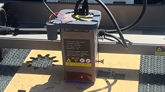
The wiring is very simple for this project. Solder your LED strip as shown:
5v --> +5v
32 --> DI
G --> GND
Be sure you're connecting to DI (data IN) rather than DO (data OUT). These strips are directional and won't work if you connect to the wrong end.
Cut a few short wires in three different colors. I like to use red for the power wire, black for ground, and white for the data line.
Solder the wires to the Mini Sparkle Motion as shown.
Slip a small piece of clear heat shrink onto the LED strip before soldering and move it down the strip until it's out of your way.
Connect the wires to your LED strip, making sure you're soldering to the IN end (the arrows printed on the strip should be pointing away from your solder joints). Connect red to 5v, black to G, and white to 32.
Plug in your microcontroller and verify that the lights come on. If you've loaded WLED they will come on in all yellow, or if you haven't done that yet they'll come on in rainbow. Either way, make sure your strip comes on before you seal it up.
To seal the strip, fill the heat shrink with a little hot glue to pot the wires in plastic. This way they're much less likely to pull off or break while you're assembling the project.
These strips are cuttable at any point. I recommend leaving the strip long until you know exactly how many lights you'll be using in your project and cutting to length during final assembly.
You'll be able to power the lights directly through the onboard USB port, and the microphone is already integrated -- so that's all the wiring which needs to be done!
This page will guide you through how to install WLED on the Mini Sparkle Motion.
The Mini Sparkle Motion has a USB to serial chip which may need a driver installed before you can install WLED. Head over to the How to Install Drivers for WCH USB to Serial Chips tutorial and download and install the new driver.
These next steps require a Web Serial-compatible browser. As of this writing, that means Google Chrome, Microsoft Edge, or Opera “desktop” browsers. Other browsers (Safari, Firefox, Explorer and anything mobile) won’t work.
Visit https://install.wled.me/
Plug your microcontroller into your computer with a known good USB cable. Click "Install" and select the port for your board.
Depending on the USB-to-serial bridge chip on the board, you might see one or two serial ports. On Mac, for instance, there might be both “/dev/cu.usbmodem[number]” and “/dev/cu.wchusbserial[number]”. Use the “wchusbserial” one.
After successful installation, enter your WiFi network name and password when prompted. This must be a 2.4 GHz WiFi network; ESP32 does not support 5 GHz networks. If it can’t connect, then as a fallback WLED will create its own 2.4 GHz WiFi access point.
If you don't see the "Connect to Wi-Fi" prompt, you'll need to set up your WiFi network using AP (access point) mode. Open up your WiFi settings and look for a WiFi network called WLED-AP. Connect to this network using the default password wled1234. The WLED interface will pop up in its own browser.
From here, go into Config/Wifi Settings and enter your WiFi credentials near the top. Give your project a name in the mDNS field a little further down the page. Now you can type in "projectname.local" (where "projectname" is your mDNS name) into any web browser on the same wifi network to access your microcontroller.
You can also scan the QR code below to open access point mode.
For more help and troubleshooting tips visit the Getting Started page on the WLED knowledge base.
Head to the WiFi Setup screen under Config and create a good URL so you can control your project from any web-enabled device. Call it something you'll remember, that's easy to type into any web browser on your WiFi network in order to connect to your project.
In Safari or Chrome on your phone or computer, type in this web address to access the WLED interface: http://projectname.local (where "projectname" is whatever you put into this field).
Check out the Additional Settings page for more info on accessing your project. WLED has an "access point mode" that doesn't require a WiFi network for when you're out on the go. It's also helpful to download one of the WLED apps to help manage and organize your projects.
Do this first before setting up your LED preferences with your GPIO number.
Click on "config" and head to the USERMODS tab. Scroll down a bit and you'll find the AudioReactive section.
Click the box to enable, then enter the settings and the Digitalmic 1section as follows:
Type: SPH0654
Pin I2S SD: 9
Pin I2S WS: 10
Pin I2S SCK: 23
The other pins are unused.
Reboot your Sparkle Motion Mini for changes to take effect.
Next, head to the LED Preferences tab under the Config menu.
Scroll down to Hardware Setup. Put your total number of LEDs into the Length field (if you're not sure yet, just put in 15), and change GPIO to pin 32, the GPIO NUMBER associated with the LED data pin on your Mini Sparkle Motion. Make sure to select the correct Color Order for your LEDs as well.
If this number appears in red and won't let you select it, check the previous step: this board is configured with pin 32 assigned to the microphone, so you need to change it there before you can set it up as your LED GPIO.
Now you can use any computer or handheld device to control your LEDs.
Make sure your device is on the same WiFi network as your board. Navigate to your custom URL (projectname.local/ ) in a web browser. You'll see a color picker above a whole bunch of color palette choices.
Choose a color, choose an effect, and watch your lights animate and glow!
Save your favorite combinations as presets, create playlists, control the speed and intensity of the animations, and lots more. This web app is incredibly intuitive and easy to use.
Head over to the WLED wiki at https://kno.wled.ge/ to delve into all the particulars.
If your lights didn't come on, here are a few things to try:
Head back to WLED and check your pinout configuration under LED Preferences. Be sure the pin number is the correct GPIO for the attachment point you used.
Check your wiring! Be sure you connected to the IN end of the LED strip. These strips can be inconsistent, so this is a pretty common problem. Use an alligator clip to try connecting the data wire on the other end (the power and ground wires should work from either end).
Try re-uploading the WLED software.
If the lights come on but you can't control them: i.e. you type in "projectname.local" into your browser and it won't connect, make sure you're on the correct WiFi network. If you're on a different network than the one you set up the software on, you won't see the WLED connection.
If your lights came on in blue or green instead of yellow, your color order is wrong. See below to fix.
If only half your lights came on, be sure you've got the correct number in the "length" field under LED preferences.
If your lights came on in a variety of weird colors and looking like a 1950s diner interior, you may have the wrong LED strip type selected. RGBW strips and RGB strips are not the same, so be sure you've got the correct strip type, or you'll get very odd behavior.
If your microcontroller hangs or keeps rebooting, or gets really hot, you may have the power and ground lines switched. Unplug right away and check: this is a fast way to brick your controller.
My .svg file has six layers. I opened them up in LightBurn and took a close look at what each layer is doing. The front layer is sparse, with a shadow tree-vein type effect. The second layer is the main trunk image, and the third and fourth layers add more depth and trunk intricacy. The fifth layer has the majority of the leaves for the tree, and the sixth layer is mostly background.
I decided to cut layer 1, 3, 4, and 6 from plywood, and layers 2 and 5 from etched acrylic. Choosing those layers worked out really well -- the trunk and leaves are the parts I want to be able to shine colors through, and I really like having a solid "resist" layer on the very top of the stack to create a shadow.
I definitely advise having two layers of wood between the two acrylic layers. This adds a 1/2 inch of separation and minimizes "bleed" from the two LED layers, leaving plenty of room to place the LED strips comfortably along the edge of the artwork and hit each acrylic layer individually.
I wanted to finish it off with a layer of acrylic mirror on the back of the design, to amplify the light and add even more depth. For this design I used gold acrylic mirror, which adds a lovely warmth to the project.
I had a few pieces of material that were 24" wide. I decided to make my project 11.5 inches wide, so I could fit two layers side-by-side with a little bit of space between them and around the edges.
Vector-based .svg files are infinitely resizable with no loss of quality. Sizing an intricate one down too much can be a problem -- if your cuts are too close together you may lose some of the integrity of the wood -- but they can be sized up as big as you'd like.
It may be a good idea to start by finding the perfect frame, and then making your project sized to fit.
Cut the wood layers out fully, using the "line" setting in LightBurn or your favorite Laser cutting software.
For the acrylic layers, you'll want to etch the design instead of cutting. I used the "fill" setting in Lightburn for these layers (but still the "line" setting to cut out the very outside edge).
Use a higher speed and lower power setting for etching. Each laser is different, so experiment to find the best settings for your laser and your plastic.
I etched the frontmost / trunk layer really lightly, so it's very translucent. A lot of the detail is behind that layer, so I didn't want to block the lower layers.
For the lower leaves layer, I used a higher power setting, so the design is almost engraved instead of etched. This layer came out a lot more opaque, but it really "pops" from deep inside the tree.
For the final back mirrored layer, I drew a 11.5" circle in LightBurn and cut out the mirror. It's a good idea to do this face down in your laser, since the mirror can reflect the laser too well and cause problems with the cut.
I used four different colors of wood stain to create some more visual depth to the piece and make the layers stand out from each other. Clean all the layers vigorously. Any little speck of dust or moisture on the plastic layers will be trapped inside and will show clearly once the lights are added.
I stacked up all the pieces and used CA glue (krazy/super glue) around the edges to secure them all together, making sure to line up the layers perfectly, since there's no getting them back apart afterwards.
I wrapped my LED strip twice around the circle, making sure the strips lay as flat as possible. I held them in place with clear packing tape, as neatly as I could.
I arranged the lights so that the microcontroller was near the bottom. Later, after I started programming animations in WLED, I did come back and do little placement-adjusting to get the strips in the right places to light the different parts of the design. The packing tape made it easy to make adjustments after the fact.
I glued the whole ensemble into the frame and attached the Mini Sparkle Motion to the back of the frame as well. I used a right-angle USB-C adapter so the USB cable can hang straight down from the back of the piece.
For this project, I wanted to light up specific LEDs in specific colors, instead of lighting the whole strip at once. This allows light up the leaf layer in different colors and animations than the trunk layer, at the same time. In WLED, this is done using Segments.
When you first set up WLED, there's one segment pre-defined, and it's called Segment 0. This segment includes all your lights: I have 108 in my project. If I run an animation on segment 0, it will run down my first strip and then seamlessly down the second or any additional strips. The LED numbers are continuous, so the segment layouts don't need to match the physical layout of the strips.
Select "solid" under effects and choose a color.
Click the "add segment" button and create a new segment. Starting with LED 1, take a guess at how many lights you should turn on to light only your top layer. Click the "check" button and look at your lights.
If all your lights are still on, click the "power" button to turn Segment 0 off and be sure the power button on the new segment is active. This should turn on LEDs 1-50, and only those LEDs.
Verify that it's lighting up the area you want and adjust the numbers if it's not.
Save this first segment before moving on. Otherwise, you may do a lot of intricate mapping work and then discover that poof! It's gone forever.
Segment layout can be saved using a Preset. Click the + Preset button and call your preset All Segments. Use the default settings and click "save".
Segments are preset-specific, meaning that different presets can (and often do) use completely different segment layouts. If you don't save your work in a preset, and then you select another preset that only has Segment 0 defined, all your segments will vanish.
This can be frustrating! So save early and save often. To update the preset after you've added more segments, click the "overwrite with state" checkbox and then click Save.
Make a segment for the LEDs that light up each of your layers.
For my project, I have one LED strip wrapped twice around my project, lighting two different acrylic layers. The first segment is set to 0-55 and the second from 55-108.
I also clicked the "Mirror Effect" box for the second segment, so the animations on each layer move in opposite directions.
Each segment can have its own animation and color choice. This is the fun part: play around and see what kind of beautiful combinations you can make.