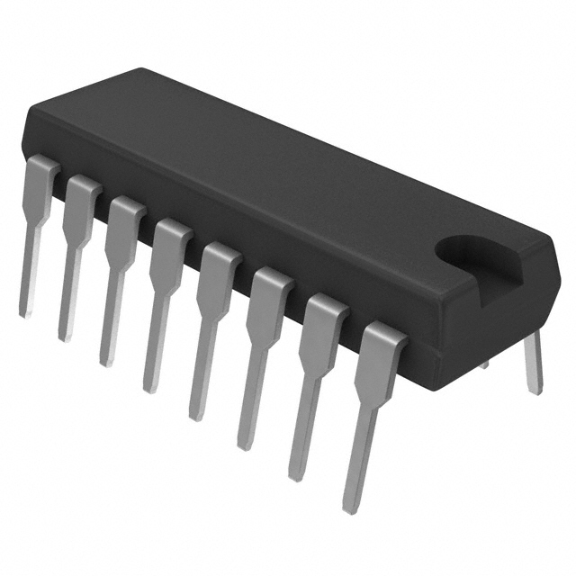
Mfr Part # NE555P
IC OSC SINGLE TIMER 100KHZ 8-DIP
Texas Instruments
License: General Public License 555 Timer Arduino
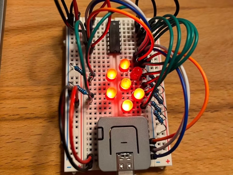
An LED chaser circuit is a fun and visually striking electronics project that creates a sequential “running light” effect with multiple LEDs. This effect is commonly used in decorative lighting, display panels, and as a beginner-friendly electronics learning project. The design integrates a 555 timer IC, configured as an astable oscillator to generate clock pulses, with a CD4017 decade counter IC to control the LED sequence.
The 555 timer is configured in astable mode, which means it continuously produces a square-wave clock signal. The frequency of this signal — and therefore the speed of the LED chaser — is controlled by a combination of resistors and capacitors, including a potentiometer for easy adjustment. This clock output appears on pin 3 of the 555 and is fed into the CD4017’s clock input.
The CD4017 is a decade counter with 10 decoded outputs (Q0–Q9). With each incoming rising clock pulse, the chip advances its active output to the next pin in sequence. Only one output is HIGH at any given time. By connecting each of these outputs to an LED (via current-limiting resistors), the LEDs light one after the other, creating the chasing effect.
When the counter reaches the last output, it automatically loops back to the first, making the pattern continuous. Additional pins, such as Reset and Clock Enable, are tied to appropriate logic levels to ensure uninterrupted counting.
Place the 555 Timer:
Insert the 555 timer IC so that pin 1 goes to ground and pin 8 goes to the positive rail.
Configure Timing Network:
Connect resistors, a potentiometer, and capacitors between the timer’s pins to set the astable frequency.
Connect the CD4017:
Position the CD4017 decade counter so that its clock input (pin 14) receives the pulse from the 555’s output.
Wire LEDs to Outputs:
Connect each LED (with a current-limiting resistor) to Q0–Q9 of the CD4017. Ensure correct polarity of LEDs.
Power and Ground Rails:
Tie both ICs to the common power and ground. Add decoupling capacitors near the ICs to reduce noise.
Test and Adjust Speed:
Power up the circuit. Turn the potentiometer to adjust chaser speed — slower resistance equals slower lighting sequence.
LED Current Limiting: Each LED should have its own resistor to prevent excessive current draw.
Power Supply: The circuit typically works with 5 V to 12 V, but most hobbyists use a 9 V battery for portability.
Troubleshooting:
If LEDs don’t blink, check the power supply and ground connections.
Ensure the clock output from the 555 reaches the CD4017 clock input.
Miswiring the reset pin on the CD4017 can stop the sequence prematurely.
Expand to More LEDs: You can cascade multiple CD4017 counters for 20 or more LEDs.
Bidirectional Chase: Add additional logic to reverse the sequence direction.
Colour & Style Variations: Swap in RGB LEDs or alternate layouts for more creative lighting patterns.
This LED Chaser Circuit with 555 Timer IC is an excellent learning project for those new to electronics and integrated circuits. It showcases fundamental concepts like pulse generation, digital counting, and sequential control using widely available ICs like the 555 timer and CD4017 decade counter. Whether for a decorative lighting effect or a stepping stone to more complex projects, this circuit is both educational and visually rewarding.