Mfr Part # 5991
ADAFRUIT USB TYPE C POWER DELIVE
Adafruit Industries LLC
License: See Original Project 3D Printing Addressable LEDs Solder / Desoldering
Courtesy of Adafruit
Guide by Ruiz Brothers
Overview
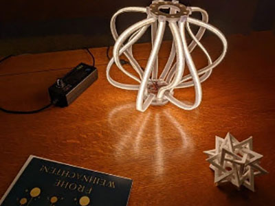
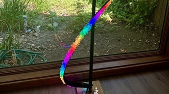
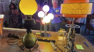
Unique LED Bulb
You can build a Victorian-era inspired lamp using an LED Noodle and 3D printed parts.
This features a 12V LED noodle that’s shaped in a zigzag pattern that wraps around a transparent 3D printed core. A glass dome fits over the LED giving this a unique aesthetic.
USB-C Power Delivery
The HUSB238 breakout is a power delivery board that lets you power devices using USB-C wall adapters with multiple voltages.
This features the HUSB238 chip, STEMMA QT for I2C control, screw block terminals and dip switches so you can easily toggle your preferred voltage.
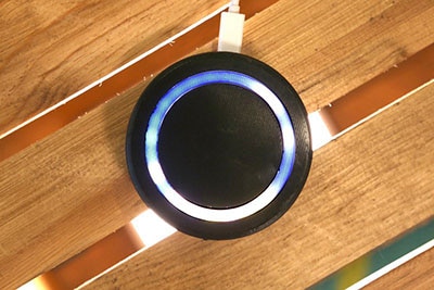
Light Switch
Mounted inside the base is a 3D printed switch that is inspired by the humble household light switch. It’s a print-in-place part that has a really satisfying click that lets you turn the lamp on and off.
Parts
Adafruit USB Type C Power Delivery Dummy - I2C or Switchable
nOOds - Flexible LED Filament - 12V 600mm long - Warm White
Silicone Cover Stranded-Core Ribbon Cable - 4 Wires 1 Meter Long
Breadboard-friendly SPDT Slide Switch
Additional Parts
1 x 7.5in Glass Dome
1 x USB PD Power Supply
USB PD power supply must be able to supply 12V at 1A minimum.
Hardware
4x M2.5 x 6mm long steel screws
10x M3 x 6mm long steel screws
4x M3 x 10mm long steel screws
2x M3 x 20mm long steel screws
2x M3 hex nuts
PLA Filament
Choose your own preferred brand and colors of filament. The colors listed below were used in this project.
1 x Gold PLA
1 x Metallic Brown PLA
1 x Silver PLA
1 x Clear PLA
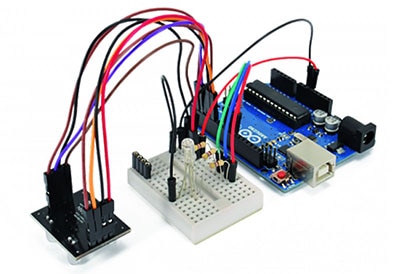
Circuit Diagram
The diagram below provides a general visual reference for wiring the components once you get to the Assembly page. This diagram was created using the software package Fritzing.
Adafruit Library for Fritzing
Adafruit uses the Adafruit Fritzing parts library to create circuit diagrams for projects. You can download the library or just grab individual parts. Get the library and parts from GitHub - Adafruit Fritzing Parts.
Wired Connections
Slide Switch
PIN#1 from switch to ON Pin (either pad) on HUSB238 Breakout
PIN#2 from switch to ON Pin (either pad) on HUSB238 Breakout
12V LED Noodle
Anode from LED to Positive pin on HUSB238 Breakout
Cathode from LED to Negative pin on HUSB238 Breakout
PD USB Power Supply
The HUSB238 Breakout is powered by a PD USB power supply (capable of 12V 1A output) into a wall outlet.
CAD Files
3D Printed Parts
STL files for 3D printing are oriented to print "as-is" on FDM style machines. Parts are designed to 3D print without any support material using PLA filament. Original design source may be downloaded using the links below.
CAD Assembly
The LED noodle is press fitted into the LED holder. The LED holder is secured to the coupler and base with screws. The LED subassembly is secured to the top base cover.
The main case is secured to the top base cover with screws. The switch plate slides into the main case. The slide switch is press fitted into the toggle switch adapter. The toggle switch is secured to the switch plate.
The bottom frame and base are secured together, then it snap fits into the main case. The HUSB238 breakout is secured to the bottom cover using screws. The bottom cover snap fits under the bottom base.
Build Volume
The parts require a 3D printer with a minimum build volume.
120mm (X) x 120 (Y) x 120mm (Z)
Transparent PLA
The LED holder looks the best when printed using a clear/transparent filament. The 3D model is thin and should only use a single parameter when 3D printed.
Design Source Files
The project assembly was designed in Fusion 360. This can be downloaded in different formats like STEP, STL and more.
Electronic components like Adafruit's boards, displays, connectors and more can be downloaded from the Adafruit CAD parts GitHub Repo.
Wiring
Set Voltage
Using a fine precision tool, enable the dip switch to set the voltage to 12V.
Wire for Switch
Use the silicone ribbon cable to create a piece of 2-wire cable that measures 7 inches in length.
Using wire strippers, remove a bit of insulation from each end of the wires.
Tin the exposed wires with a bit of solder – this prevents the wires from fraying when soldering.
Prep Switch
Use flush snips to remove one of the legs (either far left or right but not the middle).
Trim the remaining two legs so they're about half their length.
Solder Wire to Switch
Tin the legs of the switch with a bit of solder.
Attach the 2-wire cable to the two pins on the slide switch using a bit of solder.
Attach Switch Wire to HUSB Breakout
Solder the cable from the slide switch to the switch pins on the HUSB238 breakout.
Prep Resistor
Pick out a single 100ohm resistor from the pack and trim the two legs short using flush snips.
Wire for LED Noodle
Use the silicone ribbon cable to make two long wires for the LED noodle, preferably one wire with a marking to indicate polarity.
Create a piece of 2-wire cable that measures 9 inches in length.
Solder Wire to LED
Locate the end of the LED with the anode pin (the one with the hole).
Solder the marked wire to the anode pin on the LED noodle.
Heat Shrink
Add a piece of colored heat shrink tubing to the anode connection. This helps to insulate the exposed pin and denotes the voltage wire.
Continue to solder the cathode pin on the LED noodle to the remaining wire.
Add another piece of heat shrink (preferably black) to insulate the exposed connection.
Ground Wire
Locate the end of the ground wire connection and cut off about 4 inches.
Use wire stripper to remove a bit of insulation from the freshly cut wires.
The 100ohm resistor will be soldered in-line with the ground wires.
Attach Resistor
Solder the 100ohm resistor in line with the short wire and the longer ground wire.
Wired LED
Double check the 100ohm resistor has been properly soldered to the wires.
Test LED
Insert the cathode wire from the LED noodle to the negative marked screw block terminal on the HUSB238 breakout. Then use a screwdriver to secure the wire.
Secure the anode wire to the positive voltage screw block terminal.
Power the HUSB238 breakout using the USB PD wall adapter and USB-C cable.
Use the slide switch to power on the LED noodle.
LED Assembly
LED Holder
Get the 3D printed LED holder and LED noodle ready for assembly.
Clean 3D Print
Use a hobby knife to remove any excess material from the outer edge of the bottom of the 3D print.
Use caution when working with a hobby knife. Eye and hand protection would be prudent.
Installing the LED Noodle
Locate the bottom of the 3D printed LED holder. Begin fitting the two ends of the LED noodle into the channels.
Make sure the two ends of the LED noodle are in a position that is similar to the assembly photo.
Press Fitting LED
Continue to press the LED noodle into the channel, following the zigzag shape.
Repeat the installing for the opposite end of the LED noodle.
Zigzag Loop
A lengthy loop of the LED noodle should be remaining. The remaining noodle will loop over the top of the holder.
Excess Top
Loop the remaining noodle over the top of the holder and start press fitting the remainder into the closest channel.
Repeat the installation for the opposite end of the LED noodle.
Installed LED Noodle
The LED noodle should have enough length to fit through the bottom of the channel.
Double check the entire length of the LED noodle is pressed into the channels.
Test LED Noodle
Connect the positive and negative wires from the LED noodle into the corresponding pins in the HUSB238 breakouts screw-block. Use a screwdriver to secure the connections.
Power the USB breakout using a USB-C cable and the USB PD wall adapter.
Use the slide switch to power the LED noodle.
Coupler & Base
Get the LED coupler and base ready to assemble together.
Use the following hardware to secure the parts together.
2x M3 x 6mm long steel machine screws
Install LED Coupler
Press the LED coupler into the bottom of the LED holder so it is fitted into the recess.
Orient the parts so the two mounting tabs are lined up.
Install LED Base
Insert the LED wiring through the top of the LED base.
Orient the LED base so the mounting tabs are lined up with the holder and coupler.
Secure LED Base
Use the following hardware to secure the LED parts together.
2x M3 x 6mm long steel screws
Fasten the two screws to secure the LED holder, coupler, and base.
Assembled LED Holder
Take a moment to ensure all of the parts have been properly assembled.
Enclosure Assembly
Top Base Cover
Use the following hardware to secure the LED base to the top base cover.
2x M3 x 6mm steel screws
Install LED to Top Base Cover
Insert the LED wires through the center hole of the top base cover.
Place the LED base over the Top Base Cover so the mounting holes are lined up.
Insert and fasten the M3 screws to secure the LED base to the Top Base Cover.
Secured Top Base Cover
Take a moment to ensure the LED base has been properly installed to the top base cover.
Base Case Installation
Get the base case ready to attach to the top base cover. Use the following hardware to secure the parts together.
4x M3 x 10mm long steel screws
Orient the top base cover with the case so the four mounting holes in the corners are lined up.
Insert the LED wire through the top of the base case.
Secure Top Cover to Case
Begin inserting and fastening the screws to secure the top cover to the case.
Assembled Case
Take a moment to ensure the case has been properly secured to the top base cover.
Light Switch Parts
Get the three light switch parts ready to assemble. Use the following hardware.
2x M3 x 20mm long steel screws
2x M3 x 6mm long steel screws
2x M3 hex nuts
Install Plate Decal
Place the plate decal over the switch plate and line up the mounting holes.
Insert and fasten the two M3 x 6mm long screws to secure the parts together.
Install Toggle Switch Adapter
Orient the toggle switch adapter and place it into the switch plate.
Insert the toggle switch through the opening in the switch plate and line up the two mounting holes.
Secure Toggle Switch
Insert and fasten the two M3 x 20mm long machine screws through the mounting tabs.
Use the two M3 hex nuts to secure the parts together.
Install Slide Switch
Orient the slide switch with the cavity in the toggle switch.
Press fit the slide switch into the cavity in the toggle switch adapter.
Test the toggle switch mechanism by flipping the actuator.
Bottom Base & Frame
Get the bottom base and frame ready to secure together using the following hardware.
4x M3 x 6mm long machine screws
Orient the bottom base and frame so the snaps are correctly lined up. Reference the assembly photo for the correct orientation.
Place the bottom frame over the bottom case and line up the four mounting holes.
Secure Base and Frame
Insert and fasten the M3 screws through the four mounting holes to secure the parts together.
Install Light Switch Plate
The switch plate subassembly is fitted through the opening in the base case.
The outer edges will prevent the plate from falling through the opening.
Slide the switch plate all the way through the opening in the case.
Install Bottom Frame to Case
Orient the bottom frame with the case so the snaps are oriented correctly.
Secured Bottom
Firmly press the bottom frame into the case so the parts snap fit together.
HUSB238 Breakout Placement
Place the HUSB238 breakout onto the bottom cover so the mounting holes are lined up with the built-in standoffs.
Use the four M2.5 x 6mm long steel screws to secure the PCB to the standoffs.
Secure LED Wires
Insert and secure the LED wires to the HUSB238 breakout so the negative and positive are on the proper pins in the screw block.
Test Toggle Switch
Power the HUSB238 breakout using a USB-C cable and a USB PD wall adapter.
Use the toggle switch to test the LED noodle.
If the switch actuator feels incorrect, take the moment to flip and reverse the switch plate so it's in the correct orientation.
Install Bottom Cover
Orient the bottom cover with the bottom base so the USB port on the breakout is facing the port opening.
Firmly press the bottom cover into the bottom base so they are snap fitted together.
Install Glass Dome
Press the glass dome into the recess in the top base cover. It should have a nice and snug fit.
Final Build
Congratulations on your build!
Take a moment to inspect your work and ensure all of the part have been securely fastened together.