Verify Banknotes Using UV Light & IR Sensor – Touchless Arduino Project
2026-01-12 | By Ron Cutts
License: GNU Lesser General Public License Board / Sensor Interface Cables Displays Distance Infrared (IR) LED / Display Drivers LED Matrix LEDs / Discrete / Modules Arduino
In this Visuino project, you will learn how to build a touchless banknote verification system using a high-efficiency UV LED module and an IR proximity sensor in a clear and fully visual way — without writing any code.
When a banknote is placed in front of the IR proximity sensor, the Arduino instantly detects it and automatically turns ON the UV LED module for 5 seconds. This allows you to clearly see the hidden security markings on the banknote for fast and reliable verification. After 5 seconds, the UV light turns OFF automatically, ready for the next banknote.
This project is completely hands-free, making it perfect for hygienic public use, shops, kiosks, banks, and educational demonstrations.
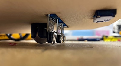
The high-efficiency UV LED module in this project uses three powerful 5mm UV LEDs that produce a strong and stable ultraviolet output. It is ideal for banknote verification, UV curing, document inspection, fluorescence testing, and scientific experiments, while remaining easy to connect directly to Arduino and other microcontroller boards.
As an optional upgrade, you can later expand this project by adding displays, buzzers, relays, or logging features — all visually in Visuino and without writing any code.
✅ Key Features of the UV LED Module
Stable UV Output – Emits a consistent 390–400nm near-UV wavelength, ideal for curing and detection tasks
Arduino-Compatible Interface – Uses the standard 3-pin (SVG) interface for quick and easy connection
Digital ON/OFF Control – Operated via a simple digital level signal from any Arduino output pin
Compact & Easy to Mount – Small size (25 × 21mm) with mounting holes for secure installation
High Power Efficiency – Produces bright UV light with minimal energy consumption, suitable for continuous use
🔬 Applications
Banknote & Document Verification – Reveal hidden security features in currency and ID cards
UV Curing – Speed up drying and hardening of UV glues, resins, and coatings
Educational & Research Projects – Ideal for chemistry labs, forensic experiments, and fluorescence testing
Environmental or Sterilization Systems – Integrate into UV sensing and sterilization projects (with proper safety precautions)
⚙️ Technical Specifications
Wavelength: 390–400nm (Near UV)
LED Type: 3 × 5mm High-Efficiency UV LEDs
Board Size: Approx. 25 × 21mm
Interface: Standard 3-Pin Arduino Interface (SVG)
Input Type: Digital Level Control
Mounting: 3mm holes, 15mm hole distance
✅ This tutorial is perfect for learning how to:
Build a touchless banknote verification system
Use a UV LED module with Arduino
Detect objects using an IR proximity sensor
Automatically turn ON a UV light for a fixed time (5 seconds)
Control everything visually using Visuino
Create reliable, hygienic, no-contact verification devices
Expand the project later with displays, alarms, relays, or data logging
You can download the full Visuino project file at the bottom and follow along step-by-step.
Watch the Video! 🎥
Step 1: What You Will Need


Arduino UNO, Nano, or any compatible Arduino board
High-Efficiency UV LED Module (3× 5mm UV LEDs)
Breadboard (Optional)
USB Cable for Arduino
Banknote for testing
Visuino Software – Download Visuino
Step 2: The Circuit

Connect Arduino [GND] to the breadboard negative rail [Black line]
Connect Arduino [5V] to the breadboard positive rail [Red line]
Connect the Infrared (IR) Obstacle Avoidance Sensor [GND] to the breadboard negative rail [Black line]
Connect the Infrared (IR) Obstacle Avoidance Sensor [VCC] to the breadboard positive rail [Red line]
Connect the Infrared (IR) Obstacle Avoidance Sensor [OUT] to Arduino digital pin [3]
Connect the UV LED Module [GND] to the breadboard negative rail [Black line]
Connect the UV LED Module [VCC] to the breadboard positive rail [Red line]
Connect the UV LED Module [IN] to Arduino digital pin [2]
💡 Note: You can easily adjust the detection sensitivity of the Infrared (IR) Obstacle Avoidance Sensor using its on-board potentiometer, allowing you to fine-tune how close the banknote must be before the UV light turns ON.
Step 3: Start Visuino, and Select the Arduino UNO Board Type


Start Visuino as shown in the first picture. Click on the "Tools" button on the Arduino component (Picture 1) in Visuino. When the dialog appears, select "Arduino UNO" as shown in Picture 2
Step 4: In Visuino, Add & Set Components


Add "Infrared (IR) Obstacle Avoidance Sensor" component
Add "Timer (Single Pulse/Clock to Digital)" component
Select "Timer1" and in the properties window set "Interval" to 5000000; this is 5s in microseconds. You can adjust this value according to your needs.
Step 5: In Visuino Connect Components
Connect "Arduino" Digital pin [3] to "ObstacleAvoidance1" pin [In]
Connect "ObstacleAvoidance1" pin [Out] to "Timer1" pin [Start]
Connect "Timer1" pin [Out] to "Arduino" Digital pin [2] pin [In]
Step 6: Generate, Compile, and Upload the Arduino Code

In Visuino, at the bottom, click on the "Build" tab, make sure the correct port is selected, and then click on the "Compile/Build and Upload" button.
Step 7: Play
Congratulations! You have completed your project with Visuino. Also attached is the Visuino project that I created for this tutorial; you can download it here and open it in Visuino: https://www.visuino.com
Download Visuino file: UV-LED-IR-OBSTACLE-SENSOR.visuino