VISUINO Rolling Dice Using 0.96 Inch 4 Pin OLED Module
2026-03-24 | By Ron Cutts
License: GNU Lesser General Public License Displays LED Strips Microcontrollers Arduino ESP32
In this tutorial, we will use OLED LCD and Visuino to make a Rolling Dice when we push a button on our breadboard.
Watch the demonstration video.
What You Will Need
For this tutorial, you will need:
Arduino uno
Breadboard (or breadboard shield)
OLED Lcd
Jumper wires
Red LED (or any other color)
Button
Pull-up resistor (50k ohm)
Visuino program: Download Visuino


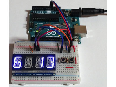
The Circuit
The connections are pretty easy; see the above image with the breadboard circuit schematic.
Connect the breadboard positive pin to the Arduino 5V pin and connect the breadboard negative pin to the Arduino GND pin.
Connect the positive pin of the LED to Arduino pin 13 and the other to the GND pin on the breadboard.
Connect the resistor pin to the breadboard positive pin and the other resistor pin to the button pin. Now connect the other button pin to the Arduino A0 pin.
Connect the OLED LCD positive pin to the breadboard positive pin and the OLED LCD negative (GND) pin to the breadboard negative pin.
Connect the OLED LCD SCL pin to the Arduino SCL pin
Connect the OLED LCD SDA pin to the Arduino SDA pin

Start Visuino, and Select the Arduino UNO board type.
To start programming the Arduino, you will need to have the Arduino IDE installed from here: http://www.arduino.cc/.
Please be aware that there are some critical bugs in Arduino IDE 1.6.6. Make sure that you install 1.6.7 or higher; otherwise, this will not work! If you have not done so already, follow the steps to set up the Arduino IDE to program the ESP8266!
The Visuino: https://www.visuino.eu also needs to be installed.
Start Visuino as shown in the first picture. Click on the "Tools" button on the Arduino component (Picture 1) in Visuino. When the dialog appears, select "Arduino Uno" as shown in Picture 2


In Visuino: Add and Connect Pulse Generator, Logic Gate, and Random Generator Component
Add Pulse Generator, set frequency to 100 (it will auto-change to 1E2); see pic 2.
Add Logic gate AND
Add Random Integer Generator, set Max:6, Min:1, and Seed:9999999


In Visuino: Add OLED LCD Component
Add OLED LCD component (picture 1)
Double-click on the OLED LCD component; the dialog window will open
On the right, select "text field" and drag it onto the left side (picture 2)
In the window "properties" set size: 9, width: 6, x: 30 (picture 3)
In the dialog window on the right, select "Fill screen" and drag it onto the left side (picture 2)
In the window "properties" set color: tmcBlack (picture 4)


In Visuino: Connecting Components
Connect Pulse Generator pin Out to logic gate component pin [1]
Connect Logic Gate pin [0] to Arduino Analog pin [A0]
Connect Logic Gate pin Out to Arduino pin Digital [13]
Connect Logic Gate pin Out to Random Integer Generator pin Clock
Random Integer Generator pin Out to Display OLED - Elements Text Field1 Pin [In]
Connect Display OLED Pin [A In] to Arduino Pin Serial [Out]
Connect Display OLED Pin [Out] to Arduino Pin I2C [In]
Connect Display OLED - Elements Fill Screen1 Pin [Clock] to Arduino Pin [A0]
Connect Arduino Serial Pin [In] to Arduino Pin [A0]

Play
If you power the Arduino Uno module, the OLED LCD will start showing random numbers once you press a button.
Congratulations! You have completed your Rolling Dice project with Visuino.
Also attached is the Visuino project that I created for this. You can download and open it in Visuino: https://www.visuino.eu